The Short Answer
Why Acceptance Testing Matters
Three audiences depend on acceptance test documentation: the customer, the cable manufacturer's warranty desk, and the future technician who will troubleshoot the system in three years.
The customer signs off on the work because the documentation proves performance to spec. Without proof, sign-off becomes a negotiation -- "is the network actually working at the rated speed?" -- with the contractor on the wrong side of the question.
The cable manufacturer's extended warranty (typically 25 years on Cat6A) requires per-link certification reports submitted within a specific time window of installation. Without those reports, the warranty does not register, and a cable failure two years later is on the contractor's dime.
The future technician troubleshooting an intermittent will compare current measurements against the as-installed baseline. If a link tested at 1.4 dB insertion loss at install and now reads 4.2 dB, the technician knows immediately that something has changed and where to look. Without baseline data, every troubleshooting call starts from zero.
Test Scope by Job Type
Acceptance test requirements vary by project. Use this table to scope the work.
| Job Type | Required Tests | Documentation |
|---|---|---|
| Residential | Visual, wiremap, length | Test results sheet, photo of patch panel |
| Small commercial (no warranty) | Visual, wiremap, length, Gigabit qualification | Per-link results spreadsheet, qualifier reports |
| Commercial with manufacturer warranty | Full TIA certification, all parameters | Per-link PDF certification reports |
| Government / healthcare / education | Full TIA certification + project-specific tests | Per-link PDFs, summary report, BICSI submission if required |
| PoE-powered devices | Standard tests + PoE injector verification | Standard docs + PoE measurement record |
| Shielded cabling | Standard tests + shield continuity + bond resistance | Standard docs + shield bonding measurements |
The Test Sequence
Run tests in this order. Each step screens out faults that would otherwise mask later steps.
Step 1: Visual inspection
Walk the entire run. Check terminations at both ends -- patch panel and outlet jack. Look for:
- Excessive untwist at terminations (Cat6/6A demand minimal untwist)
- Cable jacket damage from staples, ties, or pulled-through hardware
- Bend radius violations (Cat6/6A minimum bend radius is 4x the cable diameter)
- Cable separation from power lines (12 inches minimum from parallel power runs)
- Proper cable management (no tight bundling at terminations, gentle service loops)
- Patch panel labeling and outlet labeling consistency
Photograph any concerns. Document and remediate before electrical testing -- a visible kink will produce a measurement failure later, and finding it now saves a re-test.
Step 2: Wiremap
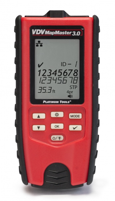
Test every link with a wiremap tester. The VDV MapMaster 3.0 or the LanSeeker performs a full wiremap in 1-2 seconds. Verify:
- All 8 conductors continuous
- No opens, shorts, or crossed pairs
- Correct TIA-568B (or 568A) pinout at both ends
- No split pairs (basic wiremap testers cannot detect this; use a tester that flags split pairs)
- Shield continuity if shielded cable
For a deeper procedure, see our continuity test guide.
Step 3: Length verification
Measure cable length on every link. Verify:
- Permanent link is 90 m or less (TIA-568 limit; allows 10 m total for patch cords)
- Channel is 100 m or less (permanent link plus patch cords)
- Length is reasonable for the documented run path (a 50-foot run measuring 200 feet means the cable took an unexpected detour)
Step 4: Gigabit qualification (if not certifying)
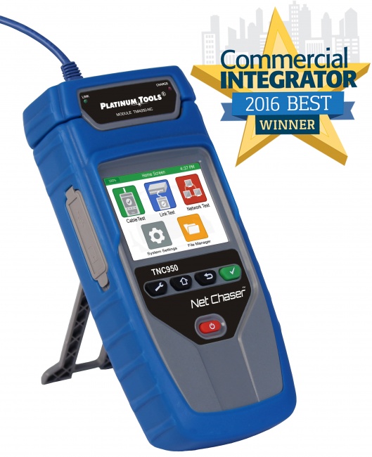
For installations not requiring TIA certification, run a qualification test that proves the link supports the target data rate. The Net Chaser validates link speeds up to 10 Gbps with actual data throughput, plus reports cable length and detects PoE.
A passing qualification result means the link works for its intended purpose. It is not a TIA certification, but it is the next-best evidence and is sufficient for most non-warranty work.
Step 5: TIA certification (when required)
For commercial work that requires manufacturer warranty registration, run a full TIA-568.2-D autotest with a Level III or higher certifier. Each link gets a complete frequency sweep across the rated bandwidth (100 MHz for Cat5e, 250 MHz for Cat6, 500 MHz for Cat6A) with all parameters measured: insertion loss, NEXT, PS-NEXT, ACR-F, PS-ACR-F, return loss, propagation delay, delay skew.
The autotest produces a per-link PDF report that becomes the customer deliverable and the warranty submission. For deeper context, see how to read certification reports and cable tester vs. certifier.
Step 6: PoE verification (when applicable)
For PoE-powered links, verify the powered path:
- Confirm injector or switch port output voltage
- Measure voltage at the device end after the cable run
- Confirm voltage drop is within tolerance (under 3 V on Cat5e/Cat6 at 100 m, under 1 V on Cat6A)
- Identify which pairs carry power (Mode A, Mode B, or 4-pair)
- Confirm current draw matches the device's specification
For full PoE procedure, see how to test PoE injector output and our PoE testing guide.
Step 7: Shield bonding (shielded cable only)
For F/UTP, U/FTP, or S/FTP installations, verify:
- Shield continuity end-to-end
- Ground bond resistance under 1 ohm at the bonded end (typically the patch panel)
- High resistance to ground at the floating end (single-point grounding)
- Under 0.5 VAC between shield and local ground at the floating end
See our shielded cable grounding test procedure.
Step 8: Documentation
Compile the per-link records into a project deliverable:
- Cable schedule (every link with ID, type, length, location)
- Test results table (link ID, pass/fail summary, test date)
- Per-link PDF reports for certified links
- Patch panel labeling diagram
- Outlet labeling map
- Photos of patch panel, IDF/MDF rooms, and any unusual cable paths
- Tester make/model/serial and last calibration date
- Technician name and date of testing
- Customer sign-off page
Pass / Fail Criteria Summary
| Test | Pass | Fail Action |
|---|---|---|
| Wiremap | All 8 conductors correct, no shorts/opens/splits | Re-terminate, re-test |
| Length (permanent link) | Under 90 m | Investigate route, consider re-pull |
| Length (channel) | Under 100 m | Shorten patch cords if possible |
| Insertion loss | Within TIA-568 spec for category | Re-terminate; check for damage |
| NEXT | Within TIA-568 spec across band | Re-terminate (most common cause: untwist) |
| Return loss | Within TIA-568 spec | Check connectors, replace patch cords |
| Throughput (qualification) | Negotiates and passes traffic at target rate | Re-terminate; re-test; replace if necessary |
| PoE voltage at PD | Within rated PD voltage range | Check cable category, terminations, injector |
| Shield bond resistance | Under 1 ohm at bonded end | Tighten bond, clean contact, replace lug |
Common Installation Defects Acceptance Testing Catches
Excessive untwist at terminations
The most common cause of NEXT failures, especially on Cat6A. Pairs untwisted more than 0.5 inch at the connector or punchdown allow crosstalk. Re-terminate with minimal untwist.
Wrong pinout (568A vs 568B mix)
One end terminated 568A, the other 568B. Wiremap shows pin 1-3 and 3-1 swap, plus 2-6 and 6-2. The link works at 10/100 (a "crossover cable") but may fail Gigabit auto-MDIX in some equipment combinations. Always document the pinout used and stay consistent throughout the project.
Crushed cable behind walls
A staple driven through the cable, a cable pinched in a clamp, or a tight bend at a corner. Wiremap may pass, but insertion loss and return loss show the damage. Use TDR to locate, then replace the damaged segment.
Patch cord problems masquerading as cable problems
A bad patch cord at either end can fail a channel test that would pass as a permanent link. Always test the channel with the actual patch cords that will be used; do not test only the permanent link and assume the channel will pass.
CCA (copper-clad aluminum) cable
Some installers inadvertently pull CCA cable from inventory thinking it is solid copper. CCA fails resistance tests, fails PoE under load, and is non-compliant with TIA-568. Verify cable markings on every box before pulling.
Mixed cable categories
A run where part of the path is Cat5e and part is Cat6 is rated only to the lower category. Verify the entire path uses the rated category, including patch cords.
Sample Documentation Package
A complete acceptance test deliverable typically includes:
- Cover sheet with project name, address, date range, contractor info, and customer sign-off line.
- Project summary -- total link count, cable types, test methodology used, pass rate.
- Cable schedule -- spreadsheet with every link ID, source location, destination location, cable type, length.
- Test results summary -- per-link pass/fail with date and technician.
- Per-link PDF reports -- automatically exported from the certifier or qualifier.
- Labeling diagrams -- patch panel layouts, outlet floor plans.
- Tester information -- make, model, serial, last calibration date.
- Photos -- patch panels, IDF/MDF rooms, anything unusual about the install.
- Warranty registration -- if applicable, manufacturer warranty submission with reference number.
Modern certifiers like Fluke DSX, NetAlly LinkRunner, and Softing WireXpert export this entire package directly to PDF. The contractor's job is review and sign-off.
Related Reading
For deeper detail on specific test types, see how to test Cat6A, cable tester vs. certifier, how to read certification reports, and the 2026 cable tester roundup.
Frequently Asked Questions
What is a network cable acceptance test?
The structured set of measurements performed on a cable installation to confirm it meets contract specifications before customer sign-off. Scope ranges from visual + wiremap (residential) to full TIA certification (commercial with warranty).
What tests are required for a Cat6 installation?
TIA-568.2-D requires wiremap, length, insertion loss, NEXT, PS-NEXT, ACR-F, PS-ACR-F, return loss, propagation delay, and delay skew across 1-250 MHz. For non-certified work, wiremap + length + Gigabit qualification is sufficient.
Should every cable be tested or just a sample?
Every cable. Sample testing is industry malpractice. Manufacturer warranties require per-link records, and per-link data becomes the baseline for future troubleshooting.
Do I need to test all 4 pairs even on a 100 Mbps run?
Yes. 10/100 Mbps uses only pairs 2 and 3, but the customer may upgrade to Gigabit (which uses all four). Test all 8 conductors at install to avoid callbacks when speeds upgrade.
What documentation should the acceptance test produce?
Per-link records with link ID, type, length, pass/fail, date, technician, and tester serial. For TIA certification, the full per-link PDF report. Plus labeling diagrams, project summary, and customer sign-off.
Build a Repeatable Acceptance Workflow
The right tester turns acceptance testing from a slog into a 10-second-per-link autotest. Browse certifiers, qualifiers, and wiremap testers built for production speed.