The Short Answer
What Continuity Testing Tells You (and Doesn't)
Continuity testing answers exactly two questions per conductor: "Is this conductor electrically connected from one end to the other?" and "Is this conductor isolated from every other conductor?" That is the entire scope.
What it catches
- Complete breaks (opens) anywhere in the conductor.
- Shorts between two conductors.
- Shorts from a conductor to shield or ground.
- Pin-to-pin miswires when probed in a wiremap pattern.
- Reversed pairs and crossed connections in multi-conductor cables.
What it does not catch
- High-frequency performance problems (NEXT, return loss, attenuation at frequency).
- Split pairs in twisted-pair cabling.
- High-resistance contacts (continuity beeps below 50 ohms; a 30-ohm cold solder joint passes the beep test but ruins data signals).
- Cable category compliance.
- Intermittent faults that do not happen during the test moment.
- Insulation degradation that has not yet caused a short.
Continuity is a screening test. It rules out the obvious problems quickly so you can focus on the harder questions. It is not a substitute for category certification or full-spectrum testing on critical infrastructure.
Equipment Options
Digital multimeter (entry level)
Any DMM with a continuity mode (the diode-with-line or speaker symbol) performs continuity testing. The meter applies a small voltage (typically 1-3 V) and beeps below a resistance threshold (usually 30-50 ohms). Multimeters are slow for multi-conductor cables -- you have to test each conductor individually -- but they are universal. A $20 meter from a hardware store works for one-off tests.
Wiremap tester
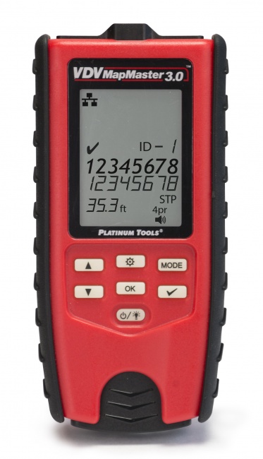
Built specifically for multi-conductor cables like Ethernet, USB, and HDMI. The unit splits into a master and a remote. Connect both ends of the cable; the master sends a signal down each conductor in sequence and the remote reports back which pin received it. The result is a complete wiremap in 1-2 seconds. The VDV MapMaster 3.0 and the LanSeeker are typical examples. Browse the full cable tester category for options.
Continuity-only LED tester
Cheap (~$20-40) Ethernet wiremap testers that show pin status with LEDs. Adequate for residential basic verification. They lack the diagnostic detail (split pair detection, high-resistance flagging) of better testers.
Pin probe
For cable types without standardized connectors -- bare-wire control cables, power cables with lugs, custom assemblies -- a pin probe (a sharp needle on a multimeter lead) makes contact with individual conductors at the termination point.
TDR for distance to fault
When continuity fails, a TDR locates the fault point along the cable. See our TDR procedure guide and browse TDR-equipped tools.
Step-by-Step Continuity Test Procedure
Step 1: De-energize the cable
Disconnect the cable from any equipment that could supply voltage. For data cables, unplug from switches and PoE injectors. For control cables, isolate the panel. For power cables, lockout-tagout. Continuity testing on energized cables produces invalid readings and can damage the meter.
Step 2: Set the meter
Switch the multimeter to continuity mode (look for the speaker icon or the diode symbol with a sound wave). Touch the two probe tips together to confirm the meter beeps and reads near zero ohms. This verifies the meter and leads are working. A meter that does not beep on a self-test is faulty -- replace the leads or the battery.
Step 3: Identify what you are testing
Note the cable type, conductor count, and connector pinouts. For a single-conductor wire, you have one continuity check to do. For 4-pair Ethernet, you have 8 conductors with a specific TIA pinout. For a 25-pair backbone, you have 50 conductors. Plan the test pattern before you start probing.
Step 4: Run conductor-to-conductor continuity
For each conductor, probe at one end and the corresponding pin or termination at the other end. Beep means continuous. No beep means open.
For multi-conductor cables, follow a structured pattern: probe pin 1 at the near end and step through pins 1 through N at the far end. Pin 1 should beep on pin 1 only. If it beeps on any other pin, you have a miswire. Document the cross-connection. Repeat for pin 2, pin 3, and so on.
Step 5: Run conductor-to-shield continuity (shielded cables only)
For shielded cables, probe each conductor against the shield/drain wire at the same connector. No beep. A beep means the conductor is shorted to shield, almost always at a damaged termination.
Step 6: Run conductor-to-conductor isolation
With both ends still disconnected, probe pairs of conductors at the same connector against each other. Pin 1 to pin 2 should not beep. Pin 1 to pin 3 should not beep. And so on through every combination. For 8-conductor Ethernet that is 28 unique pairings. Most wiremap testers do this automatically; for manual testing, work through systematically.
Step 7: Read actual resistance on suspect conductors
If continuity passes but the cable is still misbehaving, switch to the resistance range and read actual ohms. A 24 AWG copper conductor reads about 2.6 ohms per 100 meters per 100 feet. A reading 5x or 10x that figure indicates a high-resistance fault that the continuity beep missed.
Continuity Patterns by Cable Type
Ethernet (8P8C / RJ45)
Test all 8 conductors against TIA-568B pinout. Pin-to-pin continuity for 1-1, 2-2, ...8-8. Isolation for all 28 cross-pin combinations. For pair-aware testing, use a wiremap tester to detect split pairs that simple continuity misses. See our multimeter procedure for Cat5e for details.
Coax (RG-6, RG-11)
Two conductors: center pin and outer shield. Continuity center-to-center, continuity shield-to-shield, isolation center-to-shield. See our coax network testing guide.
Telephone (RJ11/RJ12)
2, 4, or 6 conductors depending on the connector. Pin-to-pin and isolation as for Ethernet, but with fewer pins.
Multi-conductor control cable
Identify each conductor by color, number, or label. Use a structured probe pattern (conductor 1 to 1, 1 to all others for isolation, then 2 to 2, etc.). Document any cross-connections found.
Backbone cable (25-pair, 50-pair, 100-pair)
Use a butt-set or a structured continuity tester designed for telecom backbones. Manual conductor-by-conductor testing is impractical at this scale.
Speaker / audio cable
Two conductors per channel, polarity-sensitive. Continuity each conductor end-to-end, isolation between conductors, plus polarity verification (positive at one end goes to positive at the other) using a polarity tester or by following the color-coded conductor.
Continuity Pass / Fail Reference
| Reading | Beep? | Interpretation | Action |
|---|---|---|---|
| 0-5 ohms | Yes | Healthy continuity | Pass; record resistance |
| 5-50 ohms | Yes | High resistance, marginal contact | Investigate terminations |
| 50 ohms - 1 megohm | No | Partial contact or contamination | Re-terminate |
| Open (OL / 1.) | No | Complete break | Replace or re-terminate; use TDR for location |
| Short (cross-pin beep) | Yes (where it should not) | Two conductors connected | Find and fix the short |
Common Continuity Test Mistakes
Testing with voltage on the line
Causes false readings and can damage the meter. Always disconnect first.
Trusting the beep alone
Continuity mode beeps below 50 ohms. A 30-ohm bad termination beeps "pass" while ruining your signal. Always follow up with a resistance reading on critical conductors.
Skipping the cross-pin isolation check
Continuity end-to-end on every pin can pass while two pins are also shorted to each other. The miswire shows a "good" continuity reading because the conductor IS continuous; you just have an extra connection that should not be there. Always run isolation between every pair of pins.
Probing the connector body instead of the pin
Many connector bodies are conductive and connect to shield, not to the signal pins. Make sure your probe contacts the actual signal pin, not the housing.
Not zeroing test lead resistance
Test leads themselves have ~0.2-0.5 ohms of resistance. On short cables, this can be a meaningful fraction of the total reading. Some meters offer a relative or REL mode to zero out the lead resistance before testing.
Frequently Asked Questions
What is a cable continuity test?
A test that confirms each conductor in a cable is unbroken end-to-end and not shorted to other conductors. The meter applies a small test voltage and measures whether current flows.
What resistance is acceptable for a continuity test pass?
Under 5 ohms for short runs is healthy. Most meters beep below 50 ohms in continuity mode, which is generous. For critical conductors, switch to the resistance range and read the actual value.
Can I do a continuity test with the cable still energized?
No. The cable must be completely de-energized. Continuity testing applies its own voltage; external voltage produces invalid readings and can damage the meter.
What is the difference between continuity and a wiremap test?
Continuity tests one conductor at a time. A wiremap test checks all conductors simultaneously and verifies pin-to-pin mapping. A wiremap is continuity plus pin-mapping, automated for multi-conductor cables.
Can a continuity test find intermittent connections?
Not reliably. The test is a snapshot. Flex the cable while watching the meter to provoke intermittents, or use a TDR to locate impedance bumps that move under flexure.
Move Beyond the Multimeter
A dedicated wiremap tester runs the entire pin-to-pin and isolation pattern in two seconds. Save the time and catch the faults a continuity beep misses.