The Short Answer
How a TDR Works
A TDR sends a fast-rising electrical pulse down the cable. The pulse travels at the cable's characteristic velocity (about 70% the speed of light for typical Cat6) until it encounters a change in impedance. Some of the pulse energy reflects back to the TDR; the rest continues forward.
The TDR records the round-trip time of every reflection. By knowing the cable's velocity of propagation, the TDR converts each round-trip time into a distance from the test point. The output is a trace -- a graph of reflection amplitude vs distance.
The amplitude and polarity of each reflection tell you what kind of discontinuity you found:
- Positive reflection -- impedance increase. Most commonly an open (broken conductor, no termination at the far end), but also kinks, tight bends, and dry-out spots in outdoor cable.
- Negative reflection -- impedance decrease. Most commonly a short (two conductors touching, conductor touching shield), but also water intrusion in outdoor cable.
- Small reflection partway down -- a connector, splice, or minor kink. Connectors typically produce a recognizable amplitude that you can ignore; significantly larger reflections suggest a faulty connector.
What You Need
The TDR itself
TDRs come in three forms relevant to network and cabling work:
- Standalone TDR with dedicated coax and twisted-pair test leads. Highest accuracy and longest range, but typically expensive ($1,500-$15,000+).
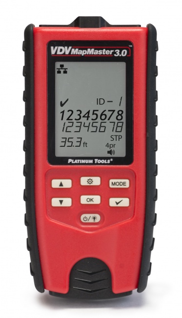
- Cable tester with built-in TDR -- many wiremap testers include a basic TDR for length measurement and rough fault distance. Accuracy is sufficient for most twisted-pair work, distance range typically up to 1,500 feet.
- Certifier with TDR -- full category certifiers include precision TDR functionality as part of the autotest. Most accurate but most expensive.
Browse TDR-equipped tools for current options.
Test leads matched to cable type
Twisted pair testing uses RJ45 plug leads. Coax testing uses F-connector or BNC leads. Some TDRs accept alligator clips for bare-wire testing. Use the lead designed for the cable; an impedance-mismatched lead creates a reflection at the lead-to-cable interface that masks the first few feet of the cable.
NVP reference table
Have the cable's specified NVP available. NVP varies by manufacturer and cable construction; using the wrong value produces incorrect distance readings.
Velocity of Propagation Reference
NVP varies by cable construction. The values below are typical; check the cable manufacturer's data sheet for exact values when available.
| Cable Type | Typical NVP | Range |
|---|---|---|
| Cat5e UTP | 0.69 | 0.65-0.72 |
| Cat6 UTP | 0.69 | 0.65-0.72 |
| Cat6A UTP | 0.69 | 0.65-0.72 |
| Cat6 F/UTP | 0.66 | 0.62-0.68 |
| Cat6A S/FTP | 0.65 | 0.62-0.70 |
| RG-6 (solid PE dielectric) | 0.66 | 0.66 |
| RG-6 (foam PE dielectric) | 0.83 | 0.83-0.85 |
| RG-11 (foam dielectric) | 0.83 | 0.83-0.85 |
| RG-59 (solid PE) | 0.66 | 0.66 |
If you do not know the cable's NVP, calibrate against a known length. Cut a piece of the same cable to a measured length, fire the TDR at it with the far end unterminated, and adjust NVP until the displayed distance matches the actual measured length. Use that NVP for all subsequent measurements on the same cable type.
Step-by-Step TDR Procedure
Step 1: De-energize and disconnect
Disconnect both ends of the cable from any equipment. The TDR's pulse can be corrupted by external signals on the line, and external voltage can damage the TDR's input circuitry.
Step 2: Connect the TDR
Plug the TDR's test lead into one end of the cable. The other end of the cable should be open (unterminated) so the far end produces a clear reflection. If the cable runs to a switch port, disconnect the cable from the switch -- the switch's input impedance is close to 100 ohms (matched to the cable) and absorbs most of the pulse, masking the far end on the TDR trace.
Step 3: Set NVP
Enter the cable's NVP into the TDR menu. If the TDR has a cable-type preset (Cat5e, RG-6, etc.), selecting it auto-loads the NVP. Otherwise enter the value manually. NVP must be set before the trace is meaningful for distance.
Step 4: Set range
Set the TDR's measurement range to roughly 1.5 to 2 times the expected cable length. Too short a range cuts off the far end reflection; too long a range compresses the trace and reduces resolution.
Step 5: Fire the pulse
Press the test button. The TDR sends the pulse and displays the reflection trace. On modern TDRs, the trace appears within a second.
Step 6: Identify the far-end reflection
On a healthy cable, the largest reflection is at the far end, where the unterminated cable presents an open circuit. The distance to this reflection is the cable length. Confirm the length matches your expectation -- if you expected 100 feet and the TDR shows 67 feet, the cable is broken at the 67-foot point and 67 feet is the distance to the fault.
Step 7: Identify intermediate reflections
Look for reflections that appear before the far-end reflection. Each one represents a discontinuity. Connectors and good splices show small reflections that you learn to recognize. Larger reflections indicate problems: kinks, water intrusion, faulty connectors, or partial shorts.
Ignore the first few inches of the trace -- the TDR's near-end dead zone obscures the connection point at the lead-to-cable interface.
Step 8: Walk the distance to the fault
Once the TDR identifies a fault location (e.g., "47 feet from the test point"), physically walk the cable from the test end and measure to that distance. Examine the cable for visible damage. The fault is usually within a few feet of the calculated point.
Step 9: Test from the other end (optional)
For long runs or when the fault is not visible at the calculated distance, repeat the test from the other end. Two distance measurements -- from each end -- triangulate the fault location and confirm the cable length.
Interpreting the Trace
| Trace Feature | Meaning | Likely Cause |
|---|---|---|
| Large positive reflection at end | Open circuit | Healthy cable, unterminated far end |
| Large negative reflection at end | Short circuit | Conductors touching at far end, or far-end equipment with shorted input |
| Smaller positive reflection partway | Impedance bump | Connector, splice, or kink |
| Large positive reflection partway | Significant open | Broken conductor or pulled-out termination |
| Large negative reflection partway | Short | Conductors touching, water intrusion, crushed cable |
| Many small reflections | Cable damage or aging | Multiple kinks, deteriorating dielectric, or rodent damage |
| Slow rise to a positive plateau | High-resistance fault | Cold solder, corroded contact, oxidation |
| No visible far-end reflection | Cable too long for range, or far end terminated | Increase range, or ensure far end is open |
Common TDR Applications
Locate breaks in installed Cat5e/Cat6
Cable that worked yesterday and does not today. Continuity testing confirms a break; the TDR finds where the break is so you can repair without replacing the entire run.
Verify cable length
For documentation, billing, or warranty registration. Many cable certifiers report length as part of their autotest using the same TDR principle.
Find water intrusion in outdoor cable
Water lowers the cable's impedance over the wetted section, producing a recognizable negative reflection. The TDR locates the wet section so you can replace just that segment.
Locate buried cable faults
Underground cable plant where the cable path is documented but the fault is hidden. The TDR's distance reading directs the excavation crew to a 5-10 foot dig area instead of trenching the entire run.
Identify aging connectors
A connector that was originally a small reflection may grow over time as oxidation builds up. Comparing TDR traces taken at installation vs. years later shows aging connectors before they fail.
Verify coax network plant
For MoCA and broadband applications where reflections from poor splitters or unterminated legs corrupt the network. See our coax network testing guide.
Related Reading
For routine continuity testing without TDR, see our continuity test procedure. For category certification (which includes TDR-derived length and propagation delay), see cable tester vs. certifier and how to test Cat6A. For tracing cables in a bundle (different from fault location), see our tone generator guide.
Frequently Asked Questions
What is a TDR and how does it work?
A Time-Domain Reflectometer sends an electrical pulse down a cable and measures reflections from any impedance discontinuity. It converts reflection time to distance using the cable's velocity of propagation, locating faults to within 1-2 feet.
What is velocity of propagation and why does it matter?
NVP is the speed of an electrical signal in a specific cable, expressed as a fraction of the speed of light. Typical Cat6 NVP is 0.69; RG-6 foam dielectric is 0.83. Wrong NVP produces wrong distance readings.
Can a TDR find a break in an underground cable?
Yes. The TDR locates the fault by distance from the test point regardless of the cable's path. Walk that distance along the documented cable route to find the fault.
What does a TDR trace look like?
A graph of reflection amplitude vs distance. Clean cable shows a flat baseline with a sharp reflection at the far end. Faults appear as bumps along the baseline -- positive for opens/kinks, negative for shorts/water.
Do I need a TDR for every cable test?
No. TDRs are diagnostic tools used when continuity testing identifies a fault and you need to find its location. For routine verification, a wiremap tester is faster and cheaper.
Find Faults the Easy Way
Stop pulling cable to find a break. A TDR locates faults to within feet on copper twisted-pair and coax runs up to thousands of feet long.