The Short Answer
What a Multimeter Can and Cannot Do
The TIA-568 standard for Cat5e specifies the cable to 100 MHz. Verifying that bandwidth requires a frequency-domain instrument that injects swept signals and measures their attenuation, reflection, and crosstalk. A multimeter is a DC instrument. It can apply a few volts and read back current or resistance. That is enough to find faults that completely break a circuit, but not enough to evaluate signal quality.
What it can find
- Opens. A broken conductor anywhere in the run shows infinite resistance.
- Shorts. Two conductors touching each other show near-zero resistance between pins that should be isolated.
- Pin mapping faults. Continuity from pin 1 at one end to pin 3 at the other proves the wiremap is wrong.
- High-resistance contacts. A cold solder joint or oxidized punchdown shows abnormally high resistance for the run length.
- Reversed pairs. Pin 1 at one end going to pin 2 at the other (and vice versa) is detectable through pin-by-pin probing.
What it cannot find
- Split pairs. The wiremap is electrically correct but uses conductors from the wrong twisted pair. The multimeter sees pass; Gigabit Ethernet sees garbage.
- NEXT, return loss, or insertion loss. All require frequency-swept measurement.
- Cable category. A multimeter cannot tell Cat5e from Cat6 or Cat3.
- Bandwidth capability. A run that passes continuity may still fail Gigabit if connector quality or termination geometry is poor.
- Length. A multimeter has no way to measure cable length without a TDR-equipped meter.
If the work is residential, low-stakes, or you just need to confirm whether a previously working cable has gone bad, the multimeter approach is fine. If the work is commercial, will be inspected, or affects production network infrastructure, plan to verify with the VDV MapMaster 3.0 or a comparable wiremap tester before signing off.
Tools You Need
Beyond the multimeter itself, the test setup requires a way to make contact with each pin on both ends. Cat5e is terminated to 8P8C plugs (commonly called RJ45) or to keystone jacks and patch panel inserts.
The basic kit
- Digital multimeter with continuity mode and a 200 ohm resistance range.
- Two RJ45 breakout adapters or a pair of dead RJ45 plugs with their conductors stripped and tagged 1 through 8. Without these, you will be probing tiny gold contacts in a plastic plug, which is unreliable.
- Alligator clips or test leads with sharp probes to land on individual pins.
- A loopback or jumper for the far end if you are testing a single-ended run. A simple paperclip jumper between two pins at the far end converts a one-end test into an in-and-out continuity check.
- The TIA-568B pinout reference, ideally taped to the inside of your toolbox lid. The pinout is the foundation of every test that follows.
The TIA-568B pinout
| Pin | Wire Color | Pair | Function (10/100) | Function (Gigabit) |
|---|---|---|---|---|
| 1 | White/Orange | 2 | TX+ | BI_DA+ |
| 2 | Orange | 2 | TX- | BI_DA- |
| 3 | White/Green | 3 | RX+ | BI_DB+ |
| 4 | Blue | 1 | Unused | BI_DC+ |
| 5 | White/Blue | 1 | Unused | BI_DC- |
| 6 | Green | 3 | RX- | BI_DB- |
| 7 | White/Brown | 4 | Unused | BI_DD+ |
| 8 | Brown | 4 | Unused | BI_DD- |
Note that pairs 1 (blue/white-blue) and 4 (brown/white-brown) carry no signal at 10/100 Mbps. A Cat5e run with damage on pair 1 or pair 4 may work fine at Fast Ethernet and fail at Gigabit. Always test all eight conductors, even if the network "works."
Step 1: Continuity Test (Both Ends Accessible)
This is the simplest scenario: both ends of the cable are physically reachable, and you can probe one end while the multimeter sits at the other.
Procedure
- Set the multimeter to continuity mode.
- Put one probe on pin 1 of the near end. Put the other probe on pin 1 of the far end.
- Listen for the beep. A beep with a near-zero resistance reading confirms the conductor is continuous.
- Move the far-end probe to pin 2, leaving the near-end probe on pin 1. Listen. You should not get a beep. If you do, you have a wiremap fault: pin 1 is wired to pin 2 instead of pin 1.
- Continue stepping the far-end probe through pins 2 through 8 with the near-end probe still on pin 1. None of those should beep. If any do, document the cross-connection.
- Move the near-end probe to pin 2 and the far-end probe to pin 2. Beep confirms continuity.
- Repeat for pins 3 through 8.
A clean cable will beep on every same-pin pair (1-1, 2-2, ...8-8) and stay silent on every cross-pin combination. If the test exposes a cross-connection, the termination at one end is wrong; redo it against the TIA-568B pinout.
Step 2: Loopback Test (One End Inaccessible)
When the far end is in a closed wall, on a roof, or 200 feet down a duct, you cannot probe both ends simultaneously. The loopback technique brings the far-end signal back to your probes by jumping pairs at the far end and reading them at the near end.
Procedure
- At the far end, install a Cat5e jack or RJ45 plug, or use a small RJ45 loopback module.
- Inside that plug, jumper pin 1 to pin 2, and pin 3 to pin 6, and pin 4 to pin 5, and pin 7 to pin 8. (You are bridging each pair to itself across the far end.)
- At the near end, set the multimeter to continuity mode.
- Probe pin 1 to pin 2. Beep confirms pair 2 is continuous all the way out and back.
- Probe pin 3 to pin 6. Beep confirms pair 3.
- Probe pin 4 to pin 5. Beep confirms pair 1.
- Probe pin 7 to pin 8. Beep confirms pair 4.
- Now check that pairs are not crossed: probe pin 1 to pin 3, pin 1 to pin 4, etc. None of these should beep.
The loopback technique only confirms that each pair is continuous and not shorted to other pairs. It does not detect a swap of pins within a pair (pin 1 and pin 2 reversed, for example). For that, you need access to both ends or a real wiremap tester.
Step 3: Short Check
A continuity test confirms each conductor is connected end-to-end. The short check confirms no conductor is touching any other conductor or shield.
Procedure
- Disconnect both ends of the cable from any equipment.
- Set the multimeter to continuity mode.
- At the near end, probe pin 1 against pin 2. No beep.
- Probe pin 1 against pins 3, 4, 5, 6, 7, and 8. None should beep.
- Move to pin 2; probe against 3, 4, 5, 6, 7, 8. None should beep.
- Continue through every pin combination. There are 28 unique pin pairs to check on an 8-conductor cable.
- If the cable is shielded, also probe each pin against the shield/drain wire. None should beep.
A short between conductors usually means a damaged jacket where two conductors have crushed together (a staple driven through the cable, a cable pinched in a clamp). It can also indicate a poor termination where stripped copper has bridged two pins inside a plug. Both faults are visible if you cut the cable open at the suspect spot.
Step 4: Resistance Check (Length Sanity)
This test catches subtle high-resistance faults that pass continuity but degrade signal quality.
Procedure
- Set the multimeter to the lowest resistance range (typically 200 ohms).
- Probe a same-pin pair through the loopback or with both ends accessible.
- Read the resistance. Subtract approximately 0.2 ohms for the test leads (or zero the meter first if it has a relative mode).
- Compare the reading to the expected value: about 2.9 ohms per 100 feet of one-way 24 AWG copper, doubled if using loopback (out and back).
- Repeat for all four pairs. All four should read within 5 to 10% of each other.
If one pair reads dramatically higher than the others, that pair has a high-resistance contact -- a bad punchdown, a corroded jack contact, or a partial wire break. If all four pairs read 30% higher than expected for the cable length, you may be looking at copper-clad aluminum (CCA) instead of solid copper, which is non-compliant and will eventually fail.
When to Upgrade to a Real Tester
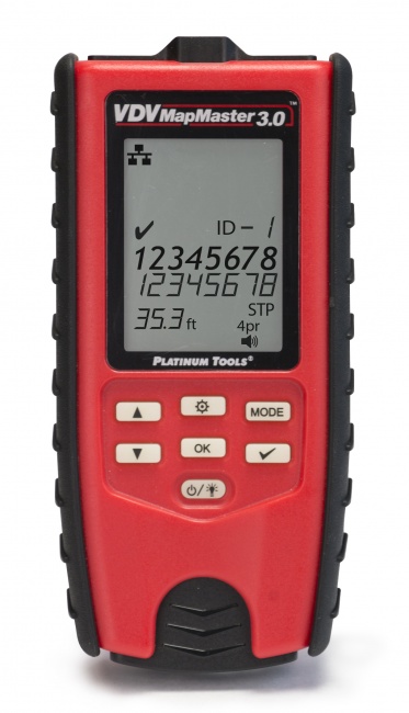
The multimeter procedure works for emergency troubleshooting and basic continuity checks. It does not replace a wiremap tester for installation work. For about $150, the VDV MapMaster 3.0 performs a complete wiremap in two seconds, detects split pairs, identifies cables in a bundle by ID, and includes a tone generator for tracing. For Gigabit qualification, the Net Chaser validates actual link speeds up to 10 Gbps.
If you find yourself reaching for the multimeter more than once a month, the time saved by a dedicated tester pays for itself in a single afternoon. For broader buying advice, see our 2026 cable tester roundup and the cable tester vs. certifier guide.
Frequently Asked Questions
Can I test Cat5e cable with a multimeter?
Yes for basic continuity, shorts, and pin mapping. No for split pairs, frequency-domain parameters, or category certification. Treat it as an emergency troubleshooting tool, not a substitute for a real tester.
What multimeter setting do I use to test cable continuity?
Continuity mode (the speaker or diode-with-line symbol). The meter beeps when resistance is below approximately 50 ohms. If continuity mode is unavailable, use the lowest resistance range and look for readings near zero ohms.
What resistance should a Cat5e conductor read?
About 2.9 ohms per 100 feet of one-way 24 AWG copper. A 50-foot run reads about 1.5 ohms; a 200-foot run reads about 5.8 ohms. Readings dramatically higher than expected suggest a high-resistance contact or copper-clad aluminum cable.
Will a multimeter find split pairs?
No. A split pair shows electrically correct continuity. Only a wiremap tester that measures pair-to-pair relationships, like the VDV MapMaster 3.0, or a frequency-domain certifier, can detect split pairs.
Can a multimeter test PoE on Cat5e?
Set to DC voltage, a multimeter can confirm 44-57 VDC is present and verify polarity, but it cannot validate the source under load or classify the PoE standard. For full PoE diagnostics, see our guide to PoE testing.
Skip the Multimeter Workaround
A real wiremap tester finds faults the multimeter misses, in a fraction of the time, with documentation you can hand to the customer.