What a Split Pair Actually Is
Twisted pair cabling depends on differential signaling. Each network signal is sent as a balanced pair of voltages, equal in magnitude and opposite in polarity, on two conductors that are physically twisted together. The twist couples both conductors equally to nearby noise sources, so common-mode noise picked up on one conductor is also picked up on the other and cancels out at the receiver. Crosstalk between adjacent pairs is also reduced because the twist alternates which conductor of each pair is closer to the adjacent pair as the cable runs.
That entire scheme depends on each signal pair being physically twisted together inside the cable. A split pair fault breaks this assumption. The pin-to-pin continuity is preserved -- pin 1 at one end is still connected to pin 1 at the other end -- but the conductor going to pin 1 is twisted with a different conductor than the one it should be paired with. The signal that is supposed to use a twisted pair is now riding on two conductors that are physically separated, while the conductor it should have been twisted with is carrying a different signal.
The crosstalk cancellation breaks. NEXT (Near-End Crosstalk) goes through the roof. The cable looks like a wiremap pass but performs like a much lower category cable. Often it cannot support its rated speed at all.
How Split Pairs Happen
Split pairs are termination errors. They are almost never caused by cable damage. The technician punching down or crimping mixed up which conductor went to which pin, in a pattern that preserves pin-to-pin continuity but breaks the pair-to-pair physical relationship.
The classic split pair pattern
The most common mistake: the installer follows the T568A or T568B pin order at one end of the cable, but at the other end uses a hybrid pattern that puts conductors in the right pin numbers but from the wrong physical pairs. Specifically, pins 3 and 6 are the easy place to introduce a split because the green and orange pairs interleave on those pins (orange-orange/white on 1-2, green/white on 3, blue and blue/white on 4-5, green on 6, brown/white-brown on 7-8 for T568B).
If the installer puts the green/white conductor on pin 3 (correct) but puts the orange conductor on pin 6 (wrong -- should be the green conductor), then re-routes the green conductor to where the orange should go, the wiremap still shows pin-to-pin continuity. But now the signal that uses pins 3 and 6 is split across the orange and green physical pairs, and the signal that uses pins 1 and 2 is similarly split.
Other causes
- Mixing T568A and T568B at the two ends without realizing -- this normally causes a crossed pair, but combined with other errors can produce a split pair
- Re-terminating with the wrong color code after the original installation, especially if the cable jacket is unmarked or the installer is colorblind
- Using pre-fab patch cords from low-quality sources -- some bargain patch cords ship with split pairs from the factory
- Damaged or worn keystone jacks where punched-down conductors have shifted positions over time
- Pin assignments changed mid-installation -- legacy phone wiring sometimes used USOC pin order, and converting to T568 standard half-way through introduces splits
Why Basic Wiremap Testers Miss Split Pairs
A basic wiremap tester places voltage on each pin in sequence and reads back which pin sees the voltage at the other end. This proves pin-to-pin continuity but says nothing about which conductors are physically twisted together. To the basic tester, a perfectly terminated cable and a split-pair cable look identical: pin 1 to pin 1, pin 2 to pin 2, all the way to pin 8.
To detect a split pair, a tester needs to evaluate the physical pairing of conductors. There are two common methods:
Capacitance-based detection (DC method)
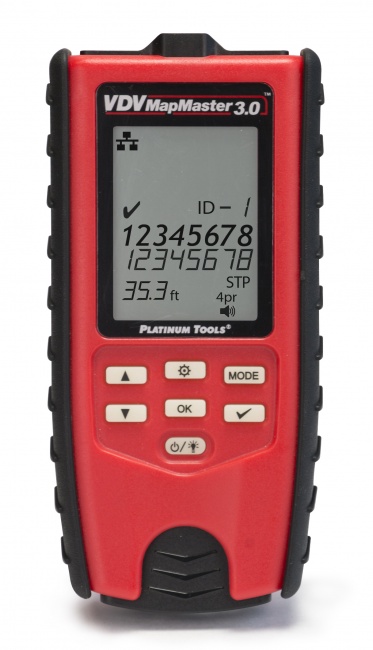
Conductors that are physically twisted together have a measurable capacitance between them that is much higher than the capacitance between conductors in different physical pairs. By measuring the capacitance between every pair of conductors at one end (with the far end open), the tester can determine which conductors are physically twisted together. If the physical pairs do not match the standard pin-pair assignments, the tester reports a split pair. This is how the VDV MapMaster 3.0 detects splits.
Crosstalk-based detection (RF method)
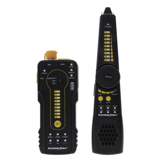
Qualification testers and certifiers detect split pairs by injecting a signal on one pair and measuring crosstalk on the other pairs. A split pair shows extremely high crosstalk because the signal pair is not actually a twisted pair -- it is two separated conductors with no twist-based isolation from the rest of the cable. Certifiers report this as a NEXT failure with a characteristic frequency response that experienced techs recognize as a split.
Symptoms a Split Pair Causes in the Field
If you suspect a split pair without a tester that can detect them, the symptom pattern is usually distinctive:
| Network Speed | Behavior on Split Pair | Why |
|---|---|---|
| 10BASE-T (10 Mbps) | Works normally | Uses only one pair, low crosstalk sensitivity |
| 100BASE-TX (100 Mbps) | Usually works, may show errors | Uses two pairs, moderate crosstalk tolerance |
| 1000BASE-T (Gigabit) | Slow throughput, packet drops, intermittent link | Uses all 4 pairs bidirectionally, very crosstalk sensitive |
| 2.5GBASE-T / 5GBASE-T | Will not negotiate or fails immediately | Higher symbol rate, even more crosstalk sensitive |
| 10GBASE-T | Will not negotiate | Cat6A NEXT requirements unattainable with split |
| PoE / PoE+ | May power on but device misbehaves | DC current imbalance across split pairs |
The classic complaint pattern: "the cable shows a green link light, but my Gigabit device is only running at 100 Mbps, and we cannot figure out why." Run a tester that detects splits before re-pulling the cable. For deeper troubleshooting context see our guide on cable testers that say fail but network works.
How to Fix a Split Pair
Step 1: Identify which end has the split
Most split pairs are introduced at one end and not the other. The other end is correctly terminated. Test from each end if your tester reports the split's location, or simply inspect both ends visually -- the wrong-pattern end often has noticeably different conductor positioning at the punch-down or crimp.
Step 2: Cut the connector and re-strip
Cut the offending connector off, leaving enough cable for a clean re-termination. Strip the cable jacket back about 1 inch. Untwist each pair only as much as needed to seat the conductors at the punch-down or crimp -- excessive untwist itself causes NEXT problems.
Step 3: Re-terminate following correct color code
Use T568A or T568B consistently across both ends of the cable. The standard pair-to-pin assignments for T568B:
- Pair 1 (blue): blue/white on pin 5, blue on pin 4
- Pair 2 (orange): orange/white on pin 1, orange on pin 2
- Pair 3 (green): green/white on pin 3, green on pin 6
- Pair 4 (brown): brown/white on pin 7, brown on pin 8
The split-pair-prone area is pins 3 through 6, where the green and blue pairs interleave. Pay particular attention to keeping the green/white and green conductors as the physical pair, with the blue and blue/white running between them on pins 4 and 5.
Step 4: Re-test
Run the wiremap test again with split pair detection enabled. Confirm pass. If the test still shows a split, the other end may also have a split, or the conductor pairing inside the cable jacket itself is incorrect (rare but possible with damaged or counterfeit cable).
Preventing Split Pairs During Installation
- Standardize on T568A or T568B across your entire crew and every project -- mixing causes splits
- Use color-coded jacks and patch panels that make the correct pair-to-pin assignment visually obvious
- Untwist no more than 1/2 inch (12 mm) for Cat6 and Cat6A -- excessive untwist causes NEXT failures even on correctly paired terminations
- Test every drop with a split-pair-capable tester as part of your installation QA, not just before sign-off
- Avoid bargain patch cords from unknown sources -- buy from reputable manufacturers and verify random samples
- Train new techs specifically on the green/blue pin 3-4-5-6 zone where most splits originate
For more on cable testing fundamentals see our guide on how to test Cat6A and cable testers vs certifiers.
Frequently Asked Questions
What is a split pair fault?
A split pair occurs when conductors are connected to the correct pin numbers but are not physically wired as the proper twisted pair. Pin-to-pin continuity is correct, but the signal pairs are split across two physical pairs in the cable, eliminating the crosstalk-cancellation benefit of pair twisting.
Why does a split pair pass a basic wiremap test?
Basic wiremap testers verify pin-to-pin continuity only. A split pair preserves this pin-to-pin mapping, so the basic wiremap shows pass. Detecting a split pair requires a tester that evaluates which conductors are physically twisted together, using either capacitance measurement or crosstalk evaluation.
What problems does a split pair cause?
Split pairs cause severe NEXT (Near-End Crosstalk) failures. The cable will typically support 10/100 Mbps Ethernet but Gigabit and faster will exhibit slow throughput, packet errors, intermittent connectivity, or complete link failure. Split pairs also cause PoE problems because of DC current imbalance.
How do I detect a split pair?
Use a tester with split pair detection capability. The VDV MapMaster 3.0 detects splits using capacitance measurement. Qualification testers like the Net Chaser detect splits during link evaluation. Certifiers detect splits as part of the full frequency sweep.
Get a Tester That Catches Split Pairs
Basic wiremap testers miss splits. Tools that find them save you from chasing phantom Gigabit and PoE problems.