How EMI Affects Network Cable
Electromagnetic fields from nearby electrical equipment couple into the conductors of any nearby cable. The coupling adds noise voltages on top of the data signal. If the noise is small relative to the signal, the receiver tolerates it and traffic flows normally. If the noise is large relative to the signal -- because the source is strong, the cable is close to the source, or the cable's noise rejection is degraded -- bit errors begin appearing.
Twisted pair cable was designed specifically to reject EMI through differential signaling: the receiver looks at the difference in voltage between the two conductors of a pair, not at the absolute voltage of either conductor. Because both conductors of a twisted pair are physically very close together, they pick up nearly identical noise from external fields. The differential receiver subtracts the noise out and recovers the data.
This noise rejection works only when the pair is actually twisted (so both conductors are equally exposed to the field) and only up to the cable's noise rejection ratio limit. Beyond that limit, the cable cannot subtract out the noise and bit errors begin.
Common EMI Sources in Commercial Spaces
Knowing the typical sources helps you predict where EMI will be a problem before installation and where to look during troubleshooting.
| Source | Frequency Range | Severity | Typical Mitigation |
|---|---|---|---|
| Variable Frequency Drive (VFD) | 1 kHz - 100 kHz, broadband harmonics | High | Increase separation, shielded cable, ferrite cores |
| Fluorescent ballasts (electronic) | 20 kHz - 40 kHz | Moderate | Separation 6+ inches |
| LED drivers (low quality) | 30 kHz - 200 kHz | Low to moderate | Separation, replace driver |
| Power transformers | 60 Hz fundamental, harmonics | Moderate to high | Separation, shielding |
| High current AC feeders | 60 Hz, harmonics | Moderate | Separation per TIA-569 |
| Two-way radios / land mobile | 30 MHz - 1 GHz | Variable, high near transmitter | Shielded cable, distance from antenna |
| Microwave ovens | 2.4 GHz | Local, intermittent | Distance, route around kitchen |
| Induction cooktops | 20 kHz - 100 kHz | Moderate, intermittent | Separation, route around |
| MRI / medical imaging | RF spectrum, very strong fields | Very high in shielded room | Faraday-shielded penetrations only |
Symptoms That Suggest EMI
EMI faults present a distinctive symptom pattern that distinguishes them from cable damage or termination problems.
Intermittent failures correlated with equipment cycles
The most diagnostic symptom: errors increase when a specific piece of equipment runs. The motor on a packaging line starts, and the network drop near the line drops out. The fluorescent fixtures come on, and the access point on that drop shows packet loss. The microwave runs, and the conference room cable has problems. Ask the customer when the problem occurs and look for a correlated event.
Switch port CRC errors
EMI shows up on switch port counters as CRC errors, alignment errors, or runts. Pull the counters on the affected port over time -- if errors come in bursts that correlate with the activity of nearby equipment, EMI is the likely cause.
Cable passes wiremap and qualification
EMI does not damage the cable, so wiremap, length, NEXT, and return loss all pass. The cable looks healthy on testing. The problem only appears when the EMI source is active and the cable is loaded with traffic. This is why EMI is often misdiagnosed -- the obvious tests all pass.
Same drop fails, neighbors are fine
Cable runs that share most of their path but diverge near the EMI source show the pattern: cables routed past the source fail, cables routed away from the source pass. If you have two drops to the same wall and one fails while the other works, look at where the cable paths diverge.
Diagnosis Workflow for Suspected EMI
Step 1: Confirm the cable is healthy
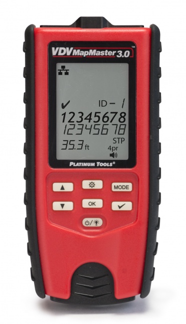
Run a wiremap test and qualification test on the affected cable. EMI shows up only as performance degradation under load -- the cable itself should pass basic tests. Use the VDV MapMaster 3.0 for wiremap and the Net Chaser for qualification.
Step 2: Pull switch port counters during failure
Capture port error counters during a failure event. CRC errors that increase rapidly during the failure point at noise on the cable. Steady-state CRC errors over time also indicate ongoing noise issues.
Step 3: Trace the cable physically
Walk the cable path from the patch panel to the wall jack. Look for: parallel runs along power conduit, paths through ceiling spaces with fluorescent fixtures or motors, sections that pass close to electrical panels, and proximity to large equipment. Note any obvious EMI source within a few feet of the cable run.
Step 4: Test correlation
If you suspect a specific source, ask the customer to cycle that equipment on and off while you monitor the network. Switch port error counts spiking when the equipment runs confirms the source.
Step 5: Apply the appropriate fix
Once you have confirmed EMI is the cause and identified the source, choose the fix.
EMI Fixes: From Cheapest to Most Involved
Re-route the cable (cheapest, often best)
Moving the cable a few feet away from the EMI source often eliminates the problem. The cable is exposed to electromagnetic field strength that decreases rapidly with distance from the source. Doubling the separation can reduce field strength by 4x. If you can re-route through a different ceiling pathway or through a different conduit run, you may have your fix in 30 minutes.
Increase separation to standard minimums
TIA-569-D specifies minimum separations between data cable and power cable based on voltage and amperage of the power circuit. The minimum is typically 2 inches for low-voltage circuits, more for higher-current feeders. If your cable is currently running closer than the standard requires, increase the separation to compliant distances.
Add ferrite cores to data cables
Snap-on ferrite cores at the equipment end of the cable add common-mode impedance that helps reject EMI coupled along the cable. Ferrites are inexpensive and can be added quickly. They are most effective against high-frequency EMI such as VFDs.
Replace with shielded cable
Shielded cable (FTP, S/FTP) provides 20-40 dB additional noise rejection over unshielded cable when the shield is properly terminated and grounded at every connection point. Shielded cable is the right answer in high-EMI environments such as factory floors and industrial facilities, but requires correct shield handling throughout the channel. A shielded cable with poorly grounded shield is worse than unshielded.
Address the EMI source
Sometimes the right fix is at the source: adding line filters to a VFD, replacing a noisy fluorescent ballast, replacing a non-compliant LED driver. This is usually outside the cabling contractor's scope but worth raising to the customer's facility manager when the source is the practical fix.
Move equipment endpoints
Sometimes the most cost-effective fix is moving the network equipment, not the cable. A wireless access point that fails because of nearby motor EMI can sometimes be relocated to a quieter spot a few feet away. The data drop stays the same; only the AP location changes.
Preventing EMI Problems During Installation
- Survey the building before pulling cable -- identify obvious EMI sources and route around them
- Maintain TIA-569 separation distances from power circuits and equipment
- Cross power cable at right angles when crossing is unavoidable; never run parallel
- Specify shielded cable for industrial areas with VFDs, motors, or other high-power equipment
- Use metal conduit as additional shielding for cable runs through high-EMI zones
- Ground patch panels and equipment racks properly to provide a path for shield drain currents
- Test cabling under operating conditions -- not just during quiet installation hours
For more on shielded cable handling see our guide on how to test shielded cable grounding.
Tools That Help With EMI Diagnosis
Network qualification tester
The Net Chaser validates throughput under load, exposing performance degradation that EMI causes during operation but not during quiet certification.
Wiremap tester
Use a basic wiremap tester to confirm the cable itself is good before pursuing EMI diagnosis. Eliminating cable defects first is essential.
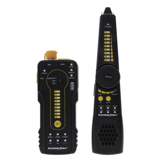
Tone generator and probe
A tone-and-probe set helps physically trace cable paths to identify where the cable runs near suspected EMI sources.
Frequently Asked Questions
How does EMI affect network cables?
EMI couples noise into the cable conductors. Twisted pair rejects most common-mode EMI through differential signaling, but strong sources can overwhelm this rejection, causing CRC errors and throughput degradation.
What are common EMI sources?
Variable frequency drives, fluorescent and LED ballasts, power transformers, high-current AC feeders, two-way radios, microwave ovens, induction cooktops, and medical imaging equipment.
Should I use shielded cable to fix EMI?
Sometimes. Shielded cable provides better EMI rejection but requires properly grounded shield termination throughout the channel. A poorly terminated shielded cable can be worse than unshielded.
How do I confirm my problem is EMI?
EMI problems correlate with equipment activity. Errors increase when nearby motors run or lighting is on. The cable passes wiremap and qualification tests but fails under load. Time the failures against equipment cycles.
Diagnose EMI Problems Before They Become Callbacks
Qualification testers, wiremap tools, and tone-and-trace sets that help you isolate EMI as the root cause.