Why Voltage Drop Is the Real PoE Constraint
The IEEE 802.3 standard caps Ethernet runs at 100 meters for data integrity. For PoE, voltage drop is the practical constraint -- and it can become a problem well before the 100-meter mark. A switch port outputs 50-57V. A powered device requires a minimum of 37V (802.3af) or 42.5V (802.3at/bt) to operate. The cable in between cannot waste more than the difference, and that difference shrinks as power requirements grow.
For 802.3af at 12.95W, the device tolerates up to 11.6V of drop. For 802.3bt Type 4 at 71.3W, the budget is tighter -- around 9V on a typical run. As wattage rises, the current through the cable rises, and current is what causes voltage drop. A 30W load on Cat5e drops more voltage than a 12W load on the same cable, simply because more current is flowing.
The result: a cable that easily handled 802.3af for years can fail when the same run is asked to deliver 802.3bt to an upgraded camera. Same cable, same length, same terminations -- but the higher-power device exposes resistance that did not matter before.
The Physics: Ohm's Law on a Twisted Pair
Voltage drop across a conductor is calculated as V = I x R, where I is current and R is total loop resistance. For a PoE run, the loop is the round-trip path: power flows out on one conductor and returns on another, so the resistance is doubled.
Loop resistance per 100 meters
Approximate DC loop resistance values for common cable gauges over 100 meters at 20 degrees Celsius:
| Cable / Gauge | Single-Conductor R / 100m | Loop R (2-pair PoE) / 100m | Loop R (4-pair PoE) / 100m |
|---|---|---|---|
| Cat5e (24 AWG) | ~9.4 ohms | ~18.8 ohms | ~9.4 ohms |
| Cat6 (23 AWG) | ~7.4 ohms | ~14.8 ohms | ~7.4 ohms |
| Cat6A (22 AWG) | ~5.9 ohms | ~11.8 ohms | ~5.9 ohms |
| CCA (24 AWG copper-clad aluminum) | ~14 ohms | ~28 ohms | ~14 ohms |
4-pair PoE (802.3bt) effectively halves the loop resistance because current is split across two parallel pairs in each direction. This is the main reason 802.3bt can deliver 90W over the same cable that 802.3at could only push 30W through.
Worked example: 802.3at on Cat5e
A 25.5W camera on a 90-meter Cat5e run, drawing roughly 0.55A through 2-pair PoE. Loop resistance at 90 meters: 0.9 x 18.8 = 16.9 ohms. Voltage drop: 0.55A x 16.9 ohms = 9.3V. If the switch outputs 53V, the camera sees 43.7V -- just above the 42.5V minimum. This run works in cool conditions but is marginal.
Same run, but Cat6
Same load on Cat6: 0.55A x 13.3 ohms (90% of 14.8 ohms loop) = 7.3V drop. Camera sees 45.7V. Comfortable margin. This is why Cat6 is recommended for any PoE+ or PoE++ install over 50 meters.
Same run, but CCA
Same load on CCA at 24 AWG: 0.55A x 25.2 ohms (90% of 28 ohms) = 13.9V drop. Camera sees 39.1V -- below the 42.5V minimum. The camera will not operate reliably. CCA is the silent killer of long-run PoE.
Temperature Makes Everything Worse
Copper resistance increases roughly 0.4% per degree Celsius. A cable installed at 20 degrees has measurably different resistance at 50 degrees -- a 12% increase. Cable bundles in conduit run warmer than open cables. Cables in attics or hot ceiling spaces run warmer still. The PoE current flowing through the cable also generates heat, raising the conductor temperature above ambient.
Real-world implications
- A run that works in winter installation can fail in summer afternoons
- Cables bundled tightly in conduit warm faster than open cables
- Outdoor cables in direct sun can exceed 60 degrees Celsius surface temperature
- For 802.3bt installs in hot climates, derate the practical run length by 10-20%
Practical Length Limits by PoE Standard and Cable
The 100-meter standard limit is the maximum for data. For reliable PoE delivery, the practical limit is shorter for higher-power applications.
| Standard / Power | Cat5e (24 AWG) | Cat6 (23 AWG) | Cat6A (22 AWG) |
|---|---|---|---|
| 802.3af (12.95W) | 100m | 100m | 100m |
| 802.3at (25.5W) | ~90m | 100m | 100m |
| 802.3bt T3 (51W) | ~80m | ~95m | 100m |
| 802.3bt T4 (71.3W) | Not recommended | ~85m | 100m |
These are practical limits with quality terminations and moderate temperature conditions. Hot environments, marginal terminations, or CCA cable shrink these numbers. For critical applications (security cameras, building access), design with 10-15% margin below the practical limit.
How to Measure Voltage Drop in the Field
Theoretical calculations are useful at design time. Field verification is what catches the problems calculations miss.
Two-point measurement
Use a PoE Pro T190 tester at the switch port and again at the device end. The difference between the two readings is the voltage drop across the run. A short patch cable to the switch port establishes the no-loss reference.
Test under load
Voltage drop is current-dependent. A test that connects the tester briefly may show acceptable voltage at the device end -- but a tester that simulates the actual device's power draw reveals the real-world drop. Some PoE testers include load simulation; for those without, connect the actual device and measure voltage at the cable termination at the wall plate while the device is operational.
Wiremap first
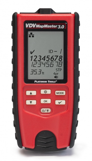
A pair fault adds infinite resistance to that pair. Verify the wiremap with a VDV MapMaster 3.0 or LanSeeker before chasing voltage drop. A "voltage drop" problem that turns out to be a broken pair shows up immediately on a wiremap test.
Use a certifier for documented runs
The Net Chaser documents cable performance with measurable parameters useful for warranty claims and compliance. For documentation that survives an audit, certifier reports are the gold standard.
Design Practices That Reduce Voltage Drop
Use Cat6 or Cat6A by default
The cost difference between Cat5e and Cat6 is minimal, and the larger conductor gauge dramatically improves PoE headroom. For new installs, Cat6 should be the default and Cat5e the exception.
Reject CCA cable at the receiving dock
Copper-clad aluminum cable has roughly 50% higher DC resistance than solid copper at the same gauge. It is non-compliant with TIA standards for PoE applications, but it shows up frequently in low-cost bulk cable sold online. Test cable rolls before installing -- a quick pull-and-burn check or specific gravity check confirms solid copper.
Move the IDF closer when runs exceed 70 meters
If multiple runs are pushing past 70-80 meters, the IDF is in the wrong place. Adding a satellite IDF closer to the high-power devices is often cheaper and more reliable than running long high-power PoE runs.
Design 802.3bt to 80% of theoretical limit
Calculate the maximum run length for the load and cable, then design to 80% of that. The margin covers temperature variation, future PoE class upgrades, and termination resistance variability.
Terminate carefully and test every termination
A single high-resistance termination -- a poorly seated keystone, an under-crimped RJ45, a corroded patch panel contact -- can add several ohms to the loop and turn a marginal run into a failed run. Termination quality is the most controllable variable in voltage drop.
Frequently Asked Questions
How much voltage drop is normal on a PoE run?
On a 90-meter Cat6 run with proper terminations, expect 1-4V drop for 802.3af loads and 3-7V for 802.3at and 802.3bt at full power. The standards allow more than this, but a drop above 5-6V on a normal-length run is a red flag for poor terminations, damaged cable, or CCA conductors.
What is the maximum cable length for PoE?
100 meters total channel length, the same as standard Ethernet. The limit is data signal integrity, not power. At 100 meters with thin cable and high-power loads, voltage drop becomes the practical constraint -- many 802.3bt Type 4 installs are unreliable past 80-90 meters.
Does cable gauge affect PoE voltage drop?
Yes. Cat6 (23 AWG) has roughly 20% lower DC resistance than Cat5e (24 AWG). On a 90-meter run powering a 30W device, the difference can be 4V drop versus 7V drop -- the difference between acceptable and marginal. For high-power, long-run PoE, larger gauge matters.
Can I use a PoE extender past 100 meters?
Yes, with caveats. Extenders re-inject power mid-run and support 200-500 meter total runs, but they are non-standard for many compliance certifications, add a failure point, and require their own power. For one-off long runs they are useful; if a building needs many extenders, the IDF is in the wrong place.
Why does my PoE camera work in cool weather and fail when hot?
Conductor resistance rises with temperature -- about 4% per 10 degrees Celsius. A run through a hot ceiling space can be 8-12% higher resistance in afternoon than morning. A run that delivers acceptable voltage when cool can drop below the device threshold under heat. Fix: shorter run, larger gauge, or thermal isolation.
Measure What Your Runs Actually Deliver
Voltage drop calculations get you in the ballpark. Field measurement gets you the truth. Pocket PoE testers, full network certifiers, and wiremap tools to verify every run.